Optical interoperability: why we need it, how we get it
Mechanical interface standards alone no longer satisfy current needs for new bandwidth-hungry, high-performance technologies.
Teodor Cotruta
Cable Design Technologies (CDT)
When mated randomly, fiber-optic connectors must comply with the optical functionality specifications required by each specific application for which they were developed. In this respect, they must satisfy a set of prescribed physical and mechanical conditions that can be separated into two principal categories: mechanical interface conditions and optical interface conditions. The boundary between these categories is not very clear and depends on where and how the performance requirements are taken into consideration.
Several mechanical interface standards were developed, one for each type of connector that succeeded in finding its own place in the market. These standards specify the sine-qua-non conditions to ensure that any combination of connectors and adapters conforming to their requirements will mechanically intermate and meet their "common level of performance."
The mechanical interface standards alone are no longer able to satisfy the current needs of the latest technologies that are hungry for bandwidth and high performance. Notions like optical interoperability and optical interface have come into focus; to address them, every standards organization is working hard to develop, as soon as possible, the demanded standards and specifications. We'll look at topics like definition, reason of being, requirements, technologies, and industry standards related to optical interoperability.
When fiber-optic connectors are used in certain applications, they are supposed to meet, in a reliable way, the performance requirements of those applications. Generally, the compliance with the performance requirements is settled between the user's procurement specifications and the supplier's product specifications. Ideally, this settlement should be based on industry standards-but these standards are not always available. The result is that a great number of users have problems in correctly defining their needs versus product availability, and a great number of suppliers have problems establishing the optimal level of performance required of their products.
The concepts of optical interoperability and optical interface attempt to fill some of the gaps existing in the system of fiber-optic standards. Let's try to find some definitions for these concepts to establish a common language here.
By optical interoperability, we can understand the possibility to interconnect randomly chosen connectors (same type of connectors taken from different production lots or from different suppliers) and still satisfy the prescribed performance requirements. The optical interface represents a set of physical and mechanical conditions that should be satisfied by optical connectors to be optically interoperable. In other words, the optical interface creates the basic conditions for the existence of optical interoperability.
To create a system of standards that addresses not only the mechanical interface conditions, but also all optical performance requirements, we must first identify all the issues that prevent the connectors from being high performance and reliable. Then the missing requirements must be added to the existing ones.
To provide the required optical performance (acceptable values for attenuation and return loss) for long-term use, the fiber-optic connectors should satisfy several physical and mechanical conditions related to the following important elements:
- Alignment of optical fibers.
- Physical contact between the fibers being joined.
- Damaged layer.
- Endface surface's quality (finish).
- Assembly procedure.
- Design and construction of mating and latching parts of the connector assembly.
The assumption is made here that all connectors employ only high-performance optical fiber. The issues related to the design and construction of mating and latching parts of the connector assembly are entirely addressed in mechanical intermateability standards-and there is no reason to discuss them here.
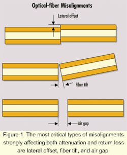
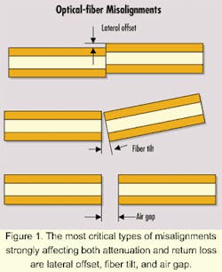
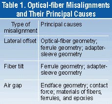
The alignment of fiber cores is a very important parameter for the low-loss transmission of light through a connection. It very much affects the attenuation of the optical signal, especially for singlemode fibers, because of their small core size. Therefore, drastic measures must be taken into consideration to limit its effects.Table 1 presents the principal types of misalignments, together with their potential causes. Some of these factors, like the ferrule outer diameter and the force exerted by the adapter sleeve on the ferrule (which indirectly represents the geometry and material of the adapter sleeve), are addressed by the mechanical intermateability standards. All the other factors, because they directly influence the optical performance of the connector, should be included among the requirements of the optical interface-at least as a reference to other standard documents or specifications where they are fully addressed.
One of the most important concepts creating the premises for high-performance connectors is without a doubt the physical contact between the joined fibers. If the alignment of optical fibers especially affects the attenuation, in contrast, the physical contact has a strong influence on return loss.
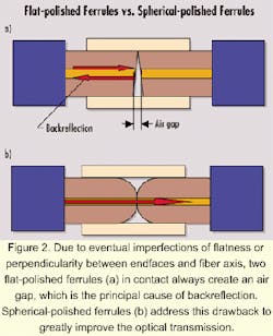
In the early days of fiber-optic connectors, their endfaces were flat-polished and an air gap always existed between the two joined fibers. That was due to small imperfections of flatness and/or perpendicularity between the endfaces and fiber axis. Not so long ago, conventional polishing practices suggested the best mating between two fibers should have a small gap to avoid direct contact of the fibers because of the eventual damage produced by it. It is known that in some particular situations, a small gap between the fibers is beneficial for improving the return loss by compensating the effect of the damaged layer resulting after polishing (all this depending on the width of the damaged layer). This practice is not recommended because it's impossible to control consistently and efficiently both the width of the damaged layer and size of the gap.Physical contact (see Figure 2) reduces (or eliminates in some situations) the Fresnel reflections generated whenever the light passes the boundary between two media with different indices of refraction, in this case, glass and air. If a gap exists between the endfaces of the fibers, multiple Fresnel reflections appear. Depending on the size of the gap, they can interfere constructively to create an important backreflection that affects the function of the active components (laser sources, amplifiers, and so on) existing in the optical link.
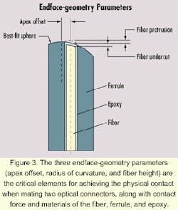
Among the elements influencing the physical contact between two mated connectors, the most important ones are the following (see Figure 3):
- Fiber height-fiber undercut/protrusion with respect to the ferrule endface.
- Apex offset-distance between the peak of the sphere that best fits the ferrule endface and the axis of the fiber.
- Radius of curvature of the ferrule endface.
- Contact force between the two mated ferrules.
- Materials-ferrule, fiber, and epoxy.
With the exception of the contact force addressed in mechanical intermateability standards, all the other parameters crucial for optical performance should be included as requirements for optical interface specifications. The first three parameters-fiber height, apex offset, and radius of curvature-are known as the endface geometry parameters, and they depend very much on the polishing process.
Several studies were made, using either finite-element or boundary-element theories, to understand the phenomena taking place during the formation of physical contact and to determine the optimal values for the endface-geometry parameters.1,2,3,4 The physical contact is achieved because of the deformation of fiber and ferrule endfaces produced by an axial compressive force (contact force).The necessary axial force to complete the physical contact is very small (e.g., around 0.016 kgf for a zirconia ferrule with a 10-mm radius of curvature and multimode optical fiber with 50-micron core diameter). The requirement established for this force is much higher (e.g., 1 kgf ± 0.2 kgf) to compensate the friction force between the ferrule and adapter sleeve (e.g., around 0.3 kgf) and the fiber withdrawal caused by environmental and/or mechanical factors such as changes in temperature and humidity as well as vibrations.
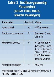
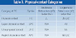
Table 2 gives the optimal values for the endface-geometry parameters for singlemode connectors, according to Telcordia Technologies standards.5 To achieve these values for the endface-geometry parameters, there needs to be developed very stable polishing processes that are controlled in manufacturing. But this can only be done with a profound understanding of the process fundamentals.The improvements in polishing techniques are obvious, and several categories of physical contact have been developed: physical contact, super physical contact, ultra physical contact, and angled physical contact. Each category corresponds to a certain level of return loss. Their usual values are represented in Table 3.
Recently, several nonconventional polishing procedures have been developed, based on the laser processing of optical surfaces. These techniques are used either in conjunction with conventional polishing methods (as the last step) or by themselves. It seems the results are excellent, especially because of the elimination of damaged layer, which is discussed later.
Very important for the achievement of good and reliable physical contact are the materials of the three principal elements: optical fiber, ferrule, and epoxy.
Silica was chosen as material for optical fibers because of its low-loss optical transmission properties. Thus, all other physical and mechanical properties are either accepted as they are or, if improved, cannot affect the optical properties.
The ferrule material should satisfy a set of conditions, among which the most important are stability during environmental changes, thermal coefficient and hardness close enough to those of glass, low Young's modulus (it deforms easily), and good-quality polished surface. Zirconia was the material of choice for ferrules because it satisfied all those conditions. In fact, the material is not pure zirconia, ZrO2 , but tetragonal zirconia polycrystal ceramic, which was stabilized by mixing pure zirconia with yttria, Y2O3. The tetragonal phase is stable up to 2,370°C, but aging at temperatures between 200° and 300°C in the presence of water could produce severe degradation of properties (e.g., ceramic could roughen and affect connector performance by increasing the frictional forces between the ferrule and adapter sleeve).6
The choice of epoxy is critical for the optical performance of a terminated connector, mostly due to the fiber pistoning caused by environmental changes, with or without loading. Epoxies with high Tg (glass transition temperature) are preferred because of reduced pistoning. Recently, a standard testing procedure7 was developed to help manufacturers choose the most appropriate epoxies for their applications.
During polishing, due to repeated impacts of the abrasive particles on the glass surface, multiple conical cracks are formed and disappear once the material is removed by complex mec hanical-chemical mechanisms. Be sides these conical cracks, some other fine cracks are formed deeper in the glass that remain even after the final polishing step.
This so-called damaged layer has a higher index of refraction than the fiberglass and strongly affects the return loss. The damaged layer can be reduced or eliminated by optimized fine polishing. However, care must be taken not to increase the fiber undercut. Otherwise, one problem is solved but another one (air gap) is created.
Important successes have been achieved with newly developed, optimized technologies, and it seems that laser polishing is a leader in this respect. It is obvious that the damaged layer should be addressed by the optical interface standards, and studies and research are being performed to better understand and evaluate it.
The endface surface quality is very important for optical performance and should be fully addressed by optical interface standards. Surface defects like scratches, cracks, and pits can appear during polishing, testing, or use because of an improper state of cleanliness and incorrect manipulations. Very limited information exists regarding how to quantify and evaluate the effects of these surface defects on attenuation and return loss. However, several current studies are underway by members of standards organizations to fill in this information void.
Besides polishing, epoxy application, and curing, during the termination of cable assemblies, other operations, if improperly done, could also strongly affect optical performance. Operations like stripping, scoring, cleaving, and crimping could be very damaging by creating stresses, cracks, and other kind of defects as well as permanent micro bends.
It is difficult to address these factors by standards requirements because it is almost impossible to quantify and measure their effects. Being pure shop practice recommendations, each manufacturer should develop appropriate technological instructions and improve them as soon as qualification and/or reliability tests show the existence of an issue.
Until recently, the standards organizations have not been very involved in optical-connector performance. For a long time, Telcordia Technologies (formerly Bellcore) was the only exception, with its GR-326-CORE, Generic Requirements for Singlemode Optical Connectors and Jumper Assemblies, which is the reference standard for telecommunications applications. This complete standard addresses interface conditions (both mechanical and optical), test procedures, performance, reliability and quality.
The International Electrotechnical Commission (IEC-Geneva) and Telecommunications Industry Association (TIA-Arlington, VA) have mechanical interface standards: the IEC-61754 series and EIA/TIA-604 series (FOCIS documents). Both organizations try to address the optical interface requirements. The Working Group 6, Standard and Specifications for Fiber-optic Connectors, inside the IEC SC86B subcommittee, is working very hard on this subject and has already prepared a first draft for "Optical Interface Standard-Part 1- General and Guidance."
Teodor Cotruta is senior fiber-optic engineer at NORDX/CDT (Quebec), a division of Cable Design Technologies, headquartered in Pittsburgh. He can be reached by e-mail at [email protected].
- T. Shintaku, R. Nagase, E. Sugita, "Connection mechanism of physical-contact optical fiber connectors with spherical convex polished ends," Applied Optics, No. 36, December 1991.
- T. Shintaku, R. Nagase, E. Sugita, "Highly stable physical-contact optical fiber connectors with spherical convex ends," Journal of Lightwave Technology, No. 2, February 1993
- L. A. Reith, P. B. Grimado, J. Brickel, "Effects of ferrule end face geometry on connector intermateability," NFOEC, June 1995.
- L. A. Reith, O.S. Gebilzlioglu, M. Koza, J. Mann, M. Ozgur, T. Bowmer, "The dimensional stability of adhesives, zirconia, and silica in optical connector ferrules and their impact on optical performance," MRS Meeting, April 1998.
- Telcordia, GR-326-CORE, Generic Requirements for Singlemode Optical Connectors and Jumper Assemblies, Issue 3, September 1999.
- R. Stevens, "An introduction to zirconia," Magnesium Elektron Ltd., 1986.
- EIA/TIA-455-194 (FOTP-194), Fiber pushback test method.
