Advances in undersea connector technology improve efficiency
Wet-mateable connectors simplify network buildouts and allow upgrades and maintenance on the seafloor.
Imagine connecting eight-way fiber-optic cable segments on the murky deep-sea floor. Sound impossible? Well, it's not. Over the last three years, seafloor fiber-optic networks have been laid in several ocean environments, including the North Sea and abyssal Pacific. The connector technology is here, and it works. It enables an operational flexibility that greatly reduces the cost of installing and maintaining seafloor communication systems.
Today's technology allows, for instance, connectorized branching units, repeaters, and universal splices. Telecommunications cables can be deployed with dormant branching points. Later, remotely operated vehicles (ROVs) or autonomously operated vehicles (AUVs) can plug in extensions as they are needed. All that is possible without the usual recovery of the parent cable or a dormant pigtail cable.
These wet-mateable connectors are rugged--tough enough to support launching through cable engines to full ocean depths, including direct burial. Undersea telecommunications cables, which heretofore have been deployed as continuous strings of segments joined by costly, time-consuming shipboard splices, can now be connectorized in advance and simply plugged together sequentially when launched, greatly reducing ship time. Another advantage of undersea systems using wet-mateable connectors is that damaged cable segments, repeaters, and branching units can be replaced at the seafloor by unplugging the devices and plugging in new ones.
Why haven't wet-mateable connectors been viable sooner? Certainly, the use of optical cables undersea is now quite mature, with the first transatlantic telecommunications cable (TAT-8) deployed in the late 1980s. Nevertheless, successfully mating optics underwater is remarkably difficult to achieve. The first undersea, wet-mateable optical connectors were offered commercially a little over a decade ago. These connectors passed only one optical circuit, and at best, were temperamental. Some used expanded-beam lenses, but the more successful designs had fiber-to-fiber physical contact junctions. To protect the optical interfaces, both the plug and receptacle contacts were housed in oil-filled chambers that were pressure-balanced to the environment. While the concept was sound, sealing and cleanliness were not adequate for complete reliability.
A second type of undersea optical connector was "dry-mateable"--it had to be mated before being deployed in water. Adding optical index-matching gel between the contact interfaces modified these connectors. The excess gel was then expelled when mating these connectors underwater. There was no attempt to exclude sand or silt from the interfaces; therefore, performance was left to chance.
Even though these first optical connectors do not meet all modern needs, until recently, nothing better had been offered, and many are still on the market. The introduction of multicircuit, all-optical (or optoelectric "hybrid"), wet-mateable connectors in mid-1996 took the existing technology another step.
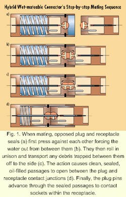
Hybrid wet-mate connectors take the best elements of the previous technology, such as oil-filled and pressure-balanced plug and receptacle housings, and combine it with a novel means for sealing and maintaining the cleanliness of the optical interfaces. Within the internal oil chambers on both the plug and receptacle, groups of contact junctions are aligned behind cylindrical, rubber face seals. When mated, opposed plug and receptacle seals first press against each other like the wringers of an old-fashioned washing machine, forcing the water out from between them.As the mating sequence continues, the opposed plug and receptacle seal, like the wringers, then roll in unison and transport off to the side any debris trapped between them. The action simultaneously causes clean, sealed, oil-filled passages to open between opposed plug and receptacle contact junctions. Continuing the mating process, plug pins advance through the sealed passages to contact sockets within the receptacle (see Fig. 1). De-mating is the reverse sequence.
These connectors are also available with electrical contacts in place of optical ones, hence the hybrid description. They work in a similar way to the optical circuits, except each mated pin/socket junction is contained in an individual, secondary, sealed oil-chamber within the common oil volume, providing a desirable additional barrier for electrical isolation. None of the contacts are ever exposed to the outside environment--before, during, or after mating. Although it sounds complicated, it results in an assembly of relatively few components.
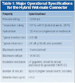
Of course, the performance of the connectors must allow their use without significant optical penalty. For that reason, wet-mateable connectors use fiber-to-fiber physical-contact junctions that give an insertion loss of less than 0.5 dB. To put that into perspective, it equates to a loss equivalent to approximately 2.5 km of fiber. Additionally, the connectors have to be capable of repeating this performance after many wet matings; thus, these devices have been designed to maintain their original performance for more than 100 mating cycles under pressure and in arduous turbid conditions. More of the connector's operational specifications are provided in the Table 1.The connector is currently available with up to eight circuits, any of which may be utilized as singlemode optical, multimode optical, or electrical passes. Due to the modular nature of the connector, this configuration is expandable to 16 or more circuits.
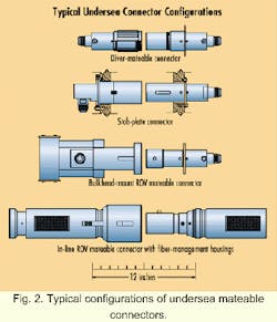
The operational "heart" of the connector can be included in a variety of connector styles (see Fig. 2). To date, the connector has been configured in the following ways:
Diver-mateable (or screw-to-connect). Suitable for use in shallower water, where it provides a compact, cost-effective connector.The flexible design of these connectors allows them to be terminated to a wide variety of cable constructions, including armored and unarmored cables, composite cables (electro-optical), and oil-filled pressure-balanced cables (see Photo 4). With the ongoing reduction in size of optical amplifiers, these too could be incorporated into the connector termination in the not-too-distant future, resulting in a compact, simplified repeater or branching unit.
The technology to enable reliable optical connections in the harsh undersea environment is available and proven. With such connectors available, deployment is expected to increase in many areas of undersea optical cabling previously stifled due to the absence of a robust connection system. Communications providers, of course, will undoubtedly benefit from the in-place upgradability, reduced maintenance costs, and other advantages gained by the underwater connection of their system components.
In addition to communications, there are anticipated requirements in oceanography (e.g., use of optical sensors), military (e.g., submarine systems), and oil and gas (e.g., undersea wellhead communications). Although very different fields of work, they all share the same desires of higher bandwidth, lighter weight, noise immunity, and secure data that optical communications provide.
Stewart Barlow is a vice president and the technical director of Ocean Design Inc. (Ormond Beach, FL).


