The growth that drives more and more traffic to a data center, in turn, drives exponentially more demand for intra- and inter-data center traffic. This phenomenon, called the “bandwidth amplification effect,” is supported by the following anecdotal evidence. If “X” amount of traffic from a user is destined for a data center, it generates 900 times that amount of traffic within the data center itself and 100 times that amount of traffic between data centers. Hence the need for more data center interconnect (DCI) bandwidth and higher line rates.
An operator can meet DCI growth demand in a couple of ways. One is to increase fiber count and the other is to increase the line data rate. Increasing the data rate is far more common and economical and is accomplished with new bandwidth-variable transponders. However, increased rates bring new issues and impairments within the optical path, which must also be addressed with ROADMs and amplifiers. Let’s consider what happens on the transponder and the issues with the optical path.
Transponder Considerations
As data transmission rates grow to 400G and beyond, a transponder will have to adjust for modulation schemes and forward error correction (FEC).
Modulation Schemes: Optical modulation is the process of encoding data into the light on a fiber-optic cable in such a way that the data can be recovered on the other end. The first optical systems used a technique called on/off keying. Basically, if light was present during a given time period, it is interpreted as 1; no light during the same time period is interpreted as 0. This is akin to shining a flashlight down a fiber and turning it off and on (very fast) using Morse code.
This technique was able to support up to 10 Gbps on each channel. Going to 100 Gbps required new technology, and the industry shifted to coherent transmission, where the light is always on, but the phase of the light and the amplitude of the light represented the data. There are a variety of modulation schemes, or ways in which the amplitude and phase of the light represent 1s and 0s. Essentially, the light is focused on points in the fiber, known as a “constellation.”
For instance, 100G line rates were achieved using dual polarization quadrature phase-shift keying (DP-QPSK), where two bits of data (four states) could be recovered from a constellation with four points (see Figure 1). Later, 200G rates used a modulation scheme called DP-16QAM (where “QAM” is quadrature amplitude modulation), with a constellation of 16 points, i.e., four bits at a time. Now, with a modulation scheme called DP-32QAM, 400G can be accomplished with a constellation of 32 points.
Figure 1. The constellations for 100G, 200G, and 400G, based on different modulation schemes.
For any specific line rate, if the receiver is close to the transmitter, the constellation is very crisp, as in the 400G example above. But as the distance between the transmitter and receiver increases, optical impairments, such as dispersion, attenuation, and various forms of distortion, cause the points to move around slightly, causing the received constellation to look “fuzzy” as illustrated in the 100G and 200G constellations. As distance increases, these points get fuzzier. Eventually, they get too fuzzy and the points overlap and cannot be distinguished on the receiving end. This is what determines maximum reach, the distance at which the points can no longer be distinguished.
There is a penalty for using a higher line rate. The larger the constellation, the closer the points and thus, the less “fuzz” that can be accommodated, as illustrated above where the points in the 400G constellation are closer together than the points in the 100G constellation. Therefore, the reach of a higher line rate with a larger constellation is limited so the points remain distinct enough for the data to be decoded.
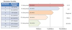
In addition to those already described, there are other modulation techniques (8QAM, 32QAM, 64QAM, and 2A8PSK among others). Exotic modifications to these techniques include 4D encoding and probabilistic modifications as well as hybrid schemes, where two modulation techniques are mixed (or more accurately, alternated). All these options enable a link to be optimized. By choosing the appropriate modulation scheme, the amount of data on that link can be maximized (see Figure 2).
Figure 2. A comparison of different modulation schemes.
Although the modulation scheme is the most important aspect, it isn’t the only transponder technology used to achieve higher line rates. To achieve these high rates, the transponder also optimizes transmit constellation compensation; enhances the launch power; applies coding gain through forward error correction, and mitigates fiber non-linearities. The techniques for most of these are highly proprietary.
FEC: In optical systems, FEC (or channel coding) is a technique used to control errors in data transmission over unreliable or noisy communication channels such as a fiber-optic link. The central idea is that the sender encodes the message in a redundant way by using an error-correcting code (ECC), and then if bits are inverted during transmission, the original message can be recovered.
FEC enables longer optical link distances. However, there is a penalty, in the form of additional overhead, for this protection. Therefore, blocks of data are encoded into larger blocks of data. This overhead is referred to as a percentage, typically anywhere from 7% to 50%; the higher the percentage, the more overhead used, but the more protection you get.
There are many FEC algorithms available, many of which are proprietary. One of the earliest and most common, still used in many transponders, is RS-FEC, or Reed-Solomon FEC. RS-FEC was introduced in the 1960s. Other common FEC algorithms are U-FEC, E-FEC, and SD-FEC. On short links with small amounts of noise, a FEC algorithm with less overhead is best, in contrast to a long and noisy path where an algorithm with greater overhead is required.
Optical Path Issues
Often-overlooked aspects of moving to higher line rates are changes to the optical path and impairments that affect the overall optical link. Specifically, it is necessary to consider changes in channel width, amplifiers, and spectral tilt.
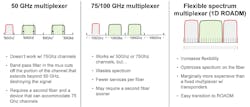
Channel Width: One of the consequences of a higher line rate is greater channel widths. 100G/200G transponders use 50-GHz channels, which are easily accommodated on the line side with a 50-GHz muxponder or a 50-GHz ROADM. But some of the new higher rate modulation schemes use 75-GHz channels. This affects the choice of device used on the optical path (see Figure 3).
If a 75-GHz signal is plugged into a 50-GHz multiplexer, the band pass filter built into the multiplexer will chop off the sides of the 75-GHz channel and destroy the signal. A fixed 75-GHz or 100-GHz multiplexer will work well, but spectrum may be wasted. A flexible-spectrum multiplexer provides optimum flexibility with flex-grid capabilities, where the bandwidth allocated is tuned to the signal.
A 1-degree ROADM will perform well as a flexible spectrum multiplexer. Typically, ROADMs are used to add and drop signals into a fiber node. In this case, since there is only one degree, there is no add and drop and you are left with a multiplexer. With a 1-degree ROADM, spectrum use on the fiber is optimized even with mixed channel-width deployments, and there is an element of future-proofing, in that it is possible to accommodate future, unknown modulation schemes with new channel widths.
Figure 3. Multiplexer options for use with higher-rate modulation schemes.
Low-Noise Amplifiers: Amplification is an aspect that deserves careful attention, since current amplifiers may not be viable, and may require replacement with new low-noise amplifiers. Most terrestrial amplifiers currently used for 100G are optimized for regional applications. An amplifier optimized for a 60-km span, but deployed on a 40-km span, would introduce twice as much noise as an amp optimized for a 40-km span. There are three sources of signal degradation in an optical link: propagation losses, signal attenuation, and equipment noise.
The sum of these three may be too large for the reduced 400G noise margin. The first two—propagation loss and signal attenuation—are fixed. But the third, equipment noise, can be minimized. Low-noise amplifiers targeted at high-speed, short-distance applications are now entering the market.
Spectral Tilt: Spectral tilt is due to non-linear attenuation in an optical transmission system. Typically, all the channels are launched into the fiber with the same amount of optical power at the transmitting end. On the receiving end, the channels have different power levels due to spectral tilt. This is illustrated in Figure 4. The slope of attenuation is spectral tilt.
Figure 4. An example of spectral tilt.
Spectral tilt does not typically affect 100G QPSK systems; although it is present at 100G rates, there is usually a large enough noise margin with this modulation format that it is not necessary to address this issue. But moving to 400G 32QAM or 600G 64QAM can lead to spectral tilt, resulting in channel loss. Due to the reduced noise margin with 400G transmission, some channels may not be recoverable. If all the channels are in use, corrective action is needed. At these high rates, it may be necessary to use tilt compensation in 1-degree ROADMs or amplifiers. To accomplish this, the ROADM or amplifier will apply pre-emphasis to the affected channels, such that they are viable at the other end.
Conclusion
We have covered some of the technologies associated with growing DCI traffic demand through higher line rates. Moving to higher line rates for DCI is an effective and economical way to address continued DCI growth. But it takes a variety of equipment upgrades and new techniques to address new optical impairments and achieve the benefits of higher line rates.
Jeff Babbitt is a principal solutions architect in the Optical Business Unit at Fujitsu Network Communications. He has more than 20 years of experience in the telecommunications industry. During that time, Jeff has remained dedicated to staying on the cutting edge of technology and sharing his knowledge through forward-thinking product planning and product management as well as technical marketing.


