By DR. BERNHARD DEUTSCH and MARK CONNER
"X" now marks the spot for new FTTx applications in wireless networks, like "A" for antenna and "T" for tower.
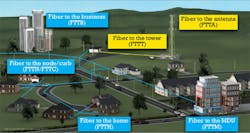
A decade ago, fiber-optic communication technology finally started to migrate deeper into access networks. However, how deep fiber would have to go to satisfy increasing bandwidth demands remained a matter of heated debate. This led to the necessity for the term "fiber to the x" (FTTx), where "x" described the network locations from which traditional copper lines would make the customer connection - typically "N" for node, "C" for curb, "B" for business, or "H" for the home. Some used "P" for premises to combine the concepts of fiber to businesses and single-family and multiple-dwelling units.
During this wireline expansion, wireless networks evolved as well, moving through 2G and 3G, focused on the connection between the cell site and the mobile devices. In the latest technology expansion, 4G wireless systems like Long Term Evolution (LTE) have begun to enable broadband wireless connections with bandwidth capabilities of several tens of megabits per second per user within the cell site's coverage area. Wireless spectrum is becoming scarce as mobile broadband data traffic shows a more than 90 percent compound annual growth rate; smartphone devices alone generate 24X the mobile data traffic of conventional wireless phones. AT&T recently reported that its mobile data volumes have surged by 8,000 percent between 2007 and 2010.
With the challenges posed by this exponential data growth, carriers strive to get their wireless signals onto a fixed-line network as quickly as possible. We therefore now see new letters added to the FTTx lexicon in the form of fiber to the tower (FTTT), or more generically "cell site" (FTTCS), since cellular transmitters are often placed on rooftops or other elevated structures such as water towers. And fiber to the antenna (FTTA) is rapidly taking fiber deeper (or higher!) as well, supplanting traditional coax in new builds and upgrades (see Figure 1).
Fiber is the new wireless app
The factors that make fiber the optimal choice for wireline and now wireless applications hold no surprise for Lightwave readers: bandwidth and signal quality. The capacity of copper cables, typically in the form of (even multiple) T1 lines, won't keep up with the backhaul traffic from an LTE-enabled cell site. Meanwhile, all-fiber access networks offer the operational cost advantages of reduced power and troubleshooting.
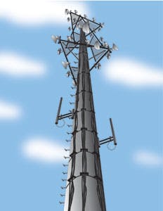
And fiber deployments to towers and rooftops provide additional benefits. Coaxial cables for cellular antennas are relatively large, often 1-5/8 or even 2-1/4 inches in diameter. A typical site requires six coaxial cables - two to each of three sectors. As an operator adds technologies and capacity, this number can double or triple. When several operators share a cell site, "tower congestion" inevitably ensues, as shown in Figure 2.
Congested towers require costly engineering surveys and complicated installations when making upgrades or additions. Coaxial cables use power inefficiently and create wind and weight loads on towers that have become a concern. Additionally, these large coaxial cables carry higher per-foot material and labor costs. And where mobile operators pay a monthly lease fee to the tower owner driven by the number and size of the components installed, operational expenses can add up.
For these reasons, it's no wonder carriers have begun to favor the smaller, lighter footprint of fiber. However, as was the case in FTTH, two obstacles had to be removed to enable FTTA deployments:
1) the cost and reliability of the active electronics
2) the cost and difficulty of the fiber installation.
The right way to wire wireless
The introduction of Remote Radio Head (RRH) technology and innovative fiber cabling has addressed these challenges. RRH technology has been available for quite some time, and major wireless equipment manufacturers have reduced the cost and improved the reliability of the components to attractive levels.
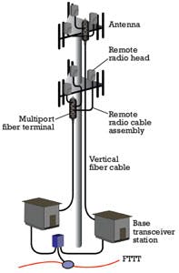
RRH technology carves the radio function out of the base station, places it at the top of the tower, and connects the two pieces via an optical signal. The optical signal is then converted into an RF signal and transmitted via a short coaxial jumper to the antennas (see Figure 3). The process is reversed for an incoming signal.
This arrangement helps provide a key RRH benefit: reduced power consumption. The long coax cable in standard architectures is reduced to a few feet. As the long cable could create a 50 percent reduction in transmit power, RRH designs thus require less energy for a given transmit power level. Meanwhile, removing the radio from the base station cabinet reduces the HVAC load and creates additional savings in power consumption.
However, cable installation of any sort at the top of a cell site poses a challenging task. Highly skilled technicians trained to work at such elevations are quite costly. Therefore, cost-effective RRH deployment requires connectivity methods that enable safe, quick installation and reliable, reconfigurable, and scalable connections.
As in the case of FTTH, hardened outside plant connectors in combination with multiport fiber terminals meet these criteria very well. The only major difference between FTTH and FTTA is the number of fibers needed for a connection: a single fiber per home for FTTH versus usually two to four fibers per RRH for FTTA. As shown in Figure 3, a multiport terminal installed at the tower-top close to the three RRHs does the trick. These multiport terminals have an integrated stub cable installed vertically on the tower; they typically connect to the active equipment in the base station cabinet via a preconnectorized end into a high-density patch panel.
In the other direction, the multiport terminals connect to the RRHs via jumper cables with a hardened multifiber connector. The multiport terminals easily accommodate future expansion in the number of RRHs, which can increase with bandwidth, spectrum. and technology additions. In a very dense situation, multiple carrier systems could even be connected from a single terminal. With three RRHs as a typical first deployment, a six-port terminal provides connections for the initial build plus three spare ports for future expansion. Port counts up to 12 are not unusual where rapid growth is expected.
Dependent upon the wireless equipment manufacturer, installers have multiple options for the connector on the RRH side of the jumper. These options range from a standard duplex LC to more specialized edge connectors. Standard duplex LCs are connected inside a sealed chamber within the RRH. Edge connectors, which include seals and protective boots, plug directly into a port on the outside wall of the RRH. An MT-based hardened fiber-optic connector used on the terminal side of the jumpers provides a well-established option with a proven track record in outside plant access networks.
Separate cables typically supply power; they often incorporate surge (over-voltage) protection. However, these power cables, combined with the fiber cable and terminal, remain much smaller and lighter than the traditional coaxial cable approach.
This plug-and-play system reduces the number of cables and components deployed. The terminal stub cable combines many homerun cables into a single sheath, while the stub and multiport terminal are integrated into a single component and part number. Compared to both large coaxial cables and homerun fiber cables, the terminal and integrated stub are much faster and easier to install. This reduces the total cost of ownership - material cost, installation time, and lease fees combined.
In summary, the need for bandwidth has pushed fiber from its former niche in long-haul backbones to the far reaches of the network. FTTCS and FTTA are just the newest "apps" on the block for fiber. Any guesses on the next letter to fall into the FTTx alphabet soup?
DR. BERNHARD DEUTSCH is vice president, global program management and MARK CONNER is global program manager, fiber to the antenna at Corning Cable Systems.


