By Daniel van der Weide
Overview
This article reviews both sampling and real-time techniques for signal conversion, compares many of the current instruments for measurement of complex modulation in fiber, and examines advantages of real-time constellation analyzers for this task.
As carriers seek to squeeze more spectral efficiency from their fiber plants while managing costs in long-haul DWDM, multilevel modulation formats beyond conventional on-off keying (OOK) become candidates for deployment. These formats include coherent dual-polarization quadrature phase-shift keying (DP-QPSK), quadrature amplitude modulation (QAM), and many variations of orthogonal frequency-division multiplexing (OFDM). All seek to optimize among competing characteristics like reach, robustness, simplicity, and spectral efficiency.
Coherent communications, using the phase of the optical carrier, has also been recognized for decades as theoretically superior to direct-detected signaling. Yet its practical implementation has only emerged with the advent of sufficiently narrow-linewidth (100 kHz to 1 MHz), frequency-stable sources together with capable hardware and digital signal processing that enable software phase-locked loops.1–3 With coherent detection, complex (quadrature) modulation with polarization diversity has the advantage of exploiting the entire electric field of the optical carrier. In addition to the obvious gains in spectral efficiency, access to these field quantities at the coherent receiver further enables mathematical filtering to compensate fully for impairments such as chromatic and polarization-mode dispersion.
Measurement overview
Although in practice OOK and differential modulation schemes are direct-detected, even these modulation formats can be optimally measured using real-time coherent detection, which translates the optical phase to electrical phase; direct detection is intensity-only. Boasting 0.5–3 THz of total bandwidth, spectral analysis and equivalent-time sampling instruments still lack the real-time bandwidth needed for robust transmission experiments with arbitrary signaling.
That said, equivalent-time sampling works well for eye diagram acquisition on repetitive signals. Meanwhile, frequency-domain instruments offer very wide total (or tuning) bandwidths with high signal-to-noise ratio (SNR) given narrow post-detection filtering. However, since they measure steady-state sinusoids, the pattern lengths frequency-domain instruments can measure are extremely short.
Coherent detection inherently enables polarization diversity for both in-phase (I) and quadrature (Q) components, a total of four tributaries per wavelength. The orthogonality of these tributaries allows each to be independently modulated. For testing, the payload of each tributary is examined, and different bit-error rates (BERs) measured on each. Typically, only the aggregate BER for all tributaries is reported, and measured with varying experimental factors, such as optical SNR, modulation format, transmitter parameters, etc.4
Coherent measurements require a phase reference, either from the original signal (homodyne), a frequency-offset reference sufficient to fully separate the down-converted spectra (heterodyne), or from a free-running, but similar-frequency-independent source. This “intradyne” method1 relies on real-time capture and digitizing of the difference-frequency waveform, whose bandwidth is the modulation (i.e., information) bandwidth plus the difference frequency. Carrier phase recovery is performed by a software phase-locked loop—removing the frequency difference between the signal and phase reference, then applying a Wiener filter to predict the phase trajectory of the signal, since the phase variations of the carrier obey a Wiener process.5
Even for differential modulation schemes that are (homodyne) direct-detected, such as differential quadrature phase-shift keying (DQPSK), a coherent receiver enables full characterization of the signal, while eliminating the phase uncertainties of a hardware delay-line interferometer (DLI), since the action of a DLI can be implemented—and even dynamically altered—in the receiver’s software.
Approaches to signal acquisition
Instruments for complex modulation in long-haul fiber must convert signals centered on ~193-THz (1,550-nm) carriers into meaningful traces on a display; this necessitates down-conversion and electrical acquisition of the down-converted signal. Just as in radio- and microwave instrumentation, there are both time- and frequency-domain methods for doing this; given the limitations of frequency-domain methods for acquiring complex-modulated signals with display update rates faster than 1 Hz, the focus here will be on time-domain techniques. Frequency-domain techniques only measure the sinusoidal steady state, glossing over fluctuations of interest for signal quality measurement.
For decades, equivalent-time sampling has been the mainstay of coherent instrumentation in both microwave instruments (such as many vector network analyzers) and sampling oscilloscopes used both for electrical and optical measurements. With electrical sampling apertures of ~3.5–7 ps, equivalent-time scopes offer 50–100-GHz total bandwidth per channel, and are used to sample the electrical output of photodiodes, e.g., in the ubiquitous Agilent 86100 DCA.
Direct optical sampling oscilloscopes (see “Characterizing advanced modulation formats using optical sampling” on page 18) also generate time-stretched replicas of the repetitive waveforms that they sample in fiber but use a pulsed laser to generate the sampling aperture and a nonlinearity (e.g., four-wave mixing) to achieve down-conversion. The EXFO PSO series is quoted as having 500 GHz of total bandwidth, implying a Gaussian sampling aperture of 0.7 ps. Both optical and electrical approaches require demodulators (e.g., hardware DLIs) to display differentially encoded signals.
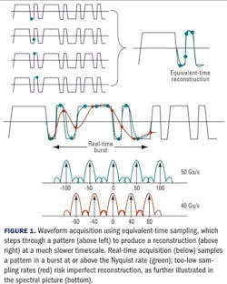
Total bandwidth, however, is distinct from instantaneous (or information) bandwidth. Equivalent-time sampling relies on repetitive acquisition of a waveform (see Fig. 1), tracing out a fast waveform slowly by stepping (sequentially or randomly) through it, but at the expense of instantaneous bandwidth, which in most electrical equivalent-time oscilloscopes is much less than 1 GHz. Even with interleaved or random sampling, this deeply sub-Nyquist (aliased) approach is limited as an evaluation tool for longer patterns, intermittent signals, and for detecting rare events, such as bit errors.
Real time
Recently, the advent of high-speed analog-to-digital (A/D) converters has enabled oscilloscopes with steadily wider instantaneous real-time bandwidths. Vendors like Agilent, LeCroy, and Tektronix offer both equivalent- and real-time oscilloscopes, with highest (four-channel) real-time bandwidths ranging from 13–20 GHz and sampling rates of 40–50 Gs/s. Bandwidth- and sampling-rate enhancement schemes allow halving the channel number to double the sample rate and increase bandwidth.6 Full-field characterization of signals in fiber, however, requires four channels: in-phase and quadrature for both X and Y polarizations.
In contrast to equivalent-time oscilloscopes, real-time scopes sample beyond the Nyquist rate (e.g., greater than two samples per cycle of the highest-frequency component in the signal). While equivalent-time samplers are deliberately highly aliased, real-time scopes require anti-aliasing filters to low-pass the input signal. The shape of these filters influences the total noise power admitted into the frontend; a steeper roll-off (i.e., more poles) maintains bandwidth while reducing noise, at the expense of complexity and risk of distortion.
Furthermore, real-time scopes operate in burst mode; instead of tracing through a repetitive waveform, they capture a burst of an arbitrary waveform (Fig. 1). The number of samples in the burst is set by the user, up to the limits of the scope’s fast waveform memory, which can be a billion points in some scopes. This burst is then processed offline; the scope does not continuously acquire data.
Distortion can also arise if the sampling rate is insufficient for the frequency content of the signal. As shown in Fig. 1, a lower sampling rate (red) will not accurately characterize a fast signal, unlike a higher sampling rate (green). For this reason, scope manufacturers are limited in the instantaneous bandwidths they can achieve with a given sampling rate, even with mathematical equalization.
Measuring multilevel, phase-encoded signals in fiber requires optical to electrical conversion, as well as translation from the ~193-THz carrier frequency of 1,550-nm light down to the modulation bandwidth of each tributary. A digitizer (e.g., an oscilloscope) with a –3-dB/octave low-pass anti-aliasing filter can measure NRZ signals at bit rates b of
But with a steeper roll-off, less broadband noise is amplified, resulting in higher SNR (Q factor), and enabling higher bit rates for the same digitizer bandwidth (BW). A more typical –9-dB/octave roll-off7 would yield
Even steeper roll-offs are characteristic of state-of-the-art oscilloscopes, so with the appropriate optical frontend, a BW=20-GHz scope (e.g., the Tektronix DSO72004B) with four channels could in principle measure greater than 150-Gbps DP-QPSK signals.
Limitations on the real-time approach are that the entire spectrum of a band is not captured at once (unlike with an optical spectrum analyzer), but instead requires tuning of the reference laser. Furthermore, the 8-bit nominal resolution of the A/D converters (with closer to 6 effective bits) gives 30- to 40-dB dynamic range, which can be greater for narrowband applications like tracking laser phase, but are still less than a state-of-the-art optical spectrum analyzer (e.g., Aragon Photonics quotes 80 dB for its BOSA).
Constellation analyzers
Analyzing complex (i.e., magnitude and phase) modulation is most generally and accurately performed with a coherent receiver. Although with an appropriate hardware demodulator (i.e., a DLI), an intensity-only instrument can be used to analyze differentially encoded signals, it cannot display the optical electric field, and it suffers a 3-dB SNR penalty versus a coherent instrument. Complete coherent receivers with optical frontends and digitizers, together with analysis software, are now being offered by both Agilent (N4391A) and Optametra (OM4106).
Serving as the optical frontend to the digitizer, a coherent reference receiver takes as input two singlemode fibers, one carrying the signal (which can be polarization-multiplexed, each polarization lit by an independent source) and the other the phase reference, or local oscillator (LO). In the receiver, the phase reference is evenly divided into both X and Y polarizations, and mixed with the signal in two branches, both I and Q. The four channels are transduced by balanced photodetectors and provided as electrical outputs, which in turn feed a real-time oscilloscope having sufficient bandwidth to capture the difference-frequency waveform.
In these constellation analyzers, the burst-mode channel data are processed to extract the tributaries associated with the modulation scheme, report measurements on the results, and display the extracted signal in several formats, including eye diagrams of each tributary, constellation (phase) diagrams of each polarization, and a Poincaré sphere plot, indicating the state of polarization (SOP) of the extracted tributaries, in the case of the Optametra approach.
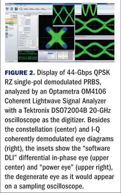
As shown in Fig. 2, the coherent constellation analyzer offers important advantages over incoherent instrumentation, particularly with RZ signaling, where the phase eyes are otherwise degenerate on a digital communications analyzer.
Daniel van der Weide is vice president, engineering, at Optametra.
References
- F. Derr, “Coherent optical QPSK intradyne system: concept and digital receiver realization,” J. Lightwave Technol. 10, pp. 1290–1296, 1992.
- M.G. Taylor, “Coherent detection method using DSP for demodulation of signal and subsequent equalization of propagation impairments,” IEEE Photonics Technol. Lett. 16, pp. 674–676, 2004.
- P.J. Winzer and R.J. Essiambre, “Advanced Optical Modulation Formats,” Proc. IEEE 94, pp. 952–985, 2006.
- M. Fuller Hanna, “Optical constellation analyzers tackle complex measurements,” Lightwave, pp. 10–14, 2009.
- M.G. Taylor, “Phase Estimation Methods for Optical Coherent Detection Using Digital Signal Processing,” IEEE J. Lightwave Technol. 27, pp. 901–914, 2009.
- P.J. Winzer, A.H. Gnauck, G. Raybon, M. Schnecker, and P.J. Pupalaikis, “56-Gbaud PDM-QPSK: Coherent Detection and 2,500-km Transmission,” ECOC 2009, Vienna, Post-deadline paper.
- Mindspeed, “NRZ Bandwidth (-3db HF Cutoff vs SNR) How Much Bandwidth is Enough?” 2003.
Links to more information
LIGHTWAVE WEBCAST: Test Strategies for 40G/100G Technology Development
LIGHTWAVE ONLINE: Optametra Coherent Lightwave Signal Analyzers Available for 100G Physical Layer Test


