by Henry Yaffe
The dynamic nature of polarization mode dispersion (PMD) makes system tolerance measurement and evaluation of systems and transponders particularly difficult. Simply defined, PMD occurs when different polarizations of the light signal travel at slightly different speeds inside a fiber, smearing the pulses. This makes reliable data transmission difficult, or even impossible, at higher data rates. Although measuring the PMD level in the optical fiber to meet established industry standards is a common practice, determining its effect on individual transponders is much more difficult to nail down.
In fact, there is no current industry standard for testing a transponder to determine the outage probabilities caused by PMD. This article will discuss characteristics of PMD and a new methodology for measuring its effect on transponders. This method provides a repeatable means of achieving quantitative outage probability results by measuring first- and second-order PMD states. This methodology is becoming the de facto standard for PMD measurement in transponder equipment-which is even more critical as both system vendors and carriers attempt to deploy 40-Gbit/sec and higher bit rate optical networks.
The key to this methodology is that it exploits a fiber’s statistics to determine the suitability of any system for deployment within the network. To make this determination, quantitative data is provided by measuring the statistically weighted cumulative outage over all PMD states for a particular transponder. With this data, an informed decision can be made on whether the equipment will perform adequately in a network deployment or if the outage probability makes deployment risky.
PMD is analogous to having “weather” in the fiber. Typically, it is clear and the light easily shines through. Occasionally, it becomes cloudy, overcast, or foggy, and visibility is diminished and limited. But there are also times-hopefully not very often-when a storm hits and nothing gets through on some wavelengths while others are experiencing completely different conditions.
Unlike other fiber-optic impairments, such as chromatic dispersion or jitter, PMD dynamically varies in time and has no wavelength correlation. Whereas jitter tolerance can be measured by making a comparison between the transponder-generated eye pattern and standard eye mask criteria under stress conditions, PMD’s statistical variations makes tolerance analysis more involved.
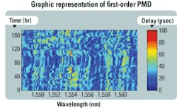
For example, Fig. 1 shows first-order PMD in a fiber. While the statistics are known, it is not possible to predict what the PMD level will be at any particular time or wavelength.
“Best effort” approaches to measuring a transponder’s PMD tolerance typically have involved the use of an emulator that attempted to mimic PMD’s erratic behavior. Basically, each transponder was connected to a PMD emulator to observe the average bit-error rate as the emulator PMD varied.
The problem is that the results cannot be used to predict failure since the PMD emulator method cannot see at which states the failures actually occur. The emulator blindly traverses the system and does not determine in what PMD states the system is degraded or fails. Second, emulators generate benign PMD states the great majority of the time. Hence, the emulator method is a very inefficient test, as it only infrequently generates the lower-probability/higher-stress PMD states that cause outages.
Because so little is understood about how the PMD conditions within the fiber degrade transponder performance, carriers and system engineers often qualitatively increase safety margins within the system to help ensure high availability of the network in the presence of PMD. Needless to say, this practice potentially wastes network resources.
Clearly, a better method of measuring PMD is needed. With the ability to quickly measure each transponder or system at the manufacturing and pre-deployment stages, informed choices can be made in terms of which equipment will provide the lowest PMD outage. For instance, no two transponders respond similarly to PMD impairment. Different manufacturer designs, and even iterations of designs, tend to behave differently. Without actually performing a measurement that achieves quantitative results, there’s no way to know how, or if, a particular transponder might “weather” PMD variations that may result in a system outage.
The bottom line is that every transponder should be measured at every level of optical system development through production and pre-deployment. Simply measuring components is not enough, since combinations of components will affect the behavior of the overall system. Another factor is that measurements must include both first-order and second-order PMD effects into optical system engineering and network deployment rules. Finally, the process must be easily repeatable for different PMD levels within the network.
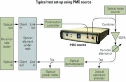
A new, more efficient methodology for PMD measurement is now available. It employs a programmable PMD source that can generate and maintain the high PMD states required to measure transponder tolerance without spending unnecessary time with the low PMD states that are not affecting the system. This device generates a wide range of first- and second-order PMD states that may be improbable on an emulator, yet typically responsible for system outages. A typical test setup using this PMD source is shown in Fig. 2.
The idea is to concentrate mainly on the “stormy” PMD states that impair the system. The first step is to make a controlled measurement by removing the dynamic PMD changes that are characteristic of fiber and emulator testing. The PMD source should generate both first- and second-order PMD states. Measuring the transponder’s optical signal-to-noise ratio (OSNR) or Q-factor degradation as a function of first- and second-order states enables the designer or system engineer to determine at what PMD states the optical system will fail and cause an outage. Even more valuable, the engineer can quantitatively predict the PMD tolerance of the system for any level of network PMD.
This is achieved in the data analysis by weighting the measured tolerance data by the known PMD statistics of the fiber. For example, if a carrier has a span with a known mean PMD of 5 psec, then the probabilities of all first- and second-order PMD states are known. The statistical likelihood of each outage measured with the PMD source is then added, or integrated, together to predict the total outage in a 5-psec span. The transponder’s outage for a span with a different PMD level can then be predicted from the same set of data. Only the statistical weighing probabilities of the first- and second-order PMD states change as the mean PMD level changes.Since this data analysis calculation is easily repeatable for various fiber PMD levels, a tremendous amount of measurements are eliminated. The amount of time spent in the lab is greatly decreased, yet the amount of useful and quantitative data is greatly increased. Uniformity of measurement is increased because the process is a standard, controlled measurement versus a random nondeterministic measurement.
Central to this methodology is that even though the transponder may fail at specific PMD states, this does not mean that the transponder is unfit to be deployed in the network. On the contrary, this method exploits the statistics. As long as the transponder failures happen at sufficiently low-probability PMD states, the statistically weighted cumulative outage over all PMD states caused by the transponder may be perfectly suitable for network deployment.
Knowledge of the PMD outage probability also provides a new network design quantity, PMD outage, that is understood by both carriers and system designers. As the industry moves toward 40-Gbit/sec optical networks and beyond, where PMD is a key obstacle, the capability of achieving quantitative data about outage probability is critical.
The transition from 10-Gbit/sec speeds to 40 Gbits/sec and beyond is significant for two reasons. First, any transition to higher line rates increases the susceptibility to PMD. In this case, the pulse is 4× narrower, so the fiber can be expected to experience 4× more PMD. Secondly, second-order PMD is proportional to bandwidth that increases at 40-Gbit/sec modulation.The fact that most carriers will be transitioning to 40 Gbits/sec on the same fiber that presently carries 10 Gbits/sec will require accurate specifications for operating 40-Gbit/sec transponders. Replacing the installed fiber is cost prohibitive and not an option for carriers. Thus, 40-Gbit/sec PMD tolerance will have to be dealt with on spans engineered originally for 10 Gbits/sec. By exploiting the quantifiable PMD outage probability results, system engineers may be able to rebalance 40-Gbit/sec system budgets between various effects to provide more system margin for higher PMD situations. Additionally, the PMD outage probability will be important to help determine what, if any, mitigation technologies are necessary.
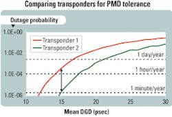
For equipment makers, system designers can use outage probability results to compare transponder designs to determine appropriate changes that improve performance. For example, Fig. 3 compares the performance of two 10-Gbit/sec transponders after the outage probability has been calculated. Armed with quantitative data and a repeatable testing methodology, engineers can set and maintain standards that will allow maximum performance and a de facto standard for measuring their systems.For carriers, quantitative outage probability enables a comparison of different systems from multiple vendors. For example, they can identify which systems will perform best on particular fiber links by determining outage probabilities for each based on the known statistics (mean PMD) for each link. Because the test is repeatable, carriers can easily and quickly qualify systems for network deployment. As carriers begin migrating their networks to 40-Gbit/sec transport speeds, this test will provide the only quantitative data available for combating the effects of PMD and ensuring reliable long-term network performance.
The best and most useful PMD tolerance testing combines both first-order and second-order PMD testing because such a combination enables more accurate predictions of system outage probabilities. First-order-only PMD testing and outage calculations typically underestimate outage, leaving both system designers and carriers exposed to unexpected outages. Measured comparisons have shown that first-order-only results can underestimate outages by more than a factor of 10!
To that end, all 10-Gbit/sec systems and, more importantly, any systems being migrated to 40 Gbits/sec should be quantified using both first-order PMD and second-order PMD stress testing. By quantifying this tolerance test data to fiber plant PMD data, network outage probability can be accurately quantified to provide a tool for both equipment manufacturers and carriers to better design, compare, and evaluate different transport systems.
Furthermore, the programmable PMD source and this test methodology enables the assessment and testing of PMD mitigation, compensation, and equalization devices for 40 Gbits/sec. This approach also becomes an indispensable tool for research and development into new modulation schemes, components, and circuits as the optical bit rate climbs from 40 Gbits/sec to 100 Gbits/sec and above.
Henry Yaffe is president of New Ridge Technologies (www.newridgetech.com), headquartered in Reisterstown, MD. He can be contacted by e-mail at [email protected].


