At the turn of the millennium, fiber inspection was performed with a microscope. This required technicians to stick their eye on a potentially live fiber, which meant risking personal injury every time they had to assess fiber endface quality.
In mid-2005, the eye care community breathed a sigh of relief when the first fiber inspection probes made their way to the market. These probes were able to display an image of the endface on an LCD rather than directly on a tech’s retina. However, this image had to be interpreted. What constituted a defect or contaminant had to be based on user knowledge and gut instinct; depending on the quality of the focus, image centering, and several other parameters, there was always a chance of misinterpretation.
By 2010, the first intelligent analysis software for fiber inspection, which was based on the IEC standard, had arrived. The software automatically detected and analyzed any defect, highlighted it on the display screen, and gave an overall pass-fail status, thereby removing the burden of interpretation and human error from the equation. Or did it?
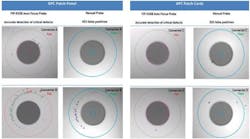
Regardless of the power of the on-board intelligence, poor focus and poor image capture will lead to errors. More often than not, an out- of-focus speck, scratch, or trace will simply not appear on the screen. The intelligent software will give the connector a thumbs up, when in reality it should not have. This is what is referred to as a “false positive.” As the saying goes, garbage in, garbage out.
Figure 1 below compares manual centering and focusing to automatic centering and focusing. The methodology involved inspecting the connector, cleaning it, and inspecting it again (with the manual focus probe) until a pass was obtained. The same port was then inspected with an automated unit.
Many papers and studies have shown the impact that connector cleanliness has on network issues and failures. Unfortunately, very few technicians, operators, and managers acknowledge this. As mentioned before, regardless of the on-board intelligence and analysis software, when the endface is slightly out-of-focus or slightly overexposed or the image is slightly off-center, false positives will occur. To truly rid the world of the connector cleanliness plague, the last remaining unknowns and variables must be removed from the equation.
The following are examples of the impact that not-so-squeaky-clean connectors can have.
Impact on higher data rates
A Tier 1 data center test covers link budget only. If it fails, the cause of the failure is not analyzed. The connectors are changed, and if that does not work, the link is broken up and shortened. This is expensive, but often cheaper than locating and troubleshooting the issue.
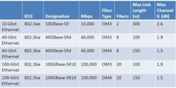
Since the standardization of Gigabit Ethernet (i.e.,1000GBASE-SX) in 2002, the 3.56-dB total channel insertion loss (IL) for 50/125-micron multimode fiber was reduced to 2.6 dB for 10GBASE- SR and to 1.9 dB for 40GBASE-SR4 (and 100GBASE-SR10; see the table below). Consequently, for 40GBASE-SR4, a maximum connector loss of 1.0 dB is required for a 150-meter channel containing multiple connector interfaces and high-bandwidth OM4 fiber. Therefore, data center upgrades to higher data rates such as 40G and 100G may fail because the tolerance to IL becomes much tighter.
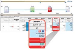
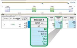
After cleaning the connectors, the loss reading dropped to 0.053 dB at 1310 nm, with a reflectance of -55.9 dB. The link ORL also dropped to 50.4 dB. Everything is back to normal (Figure 3).
If we apply these results to the data center example above, only three of these bad connections would have failed at 40G data rates and higher.
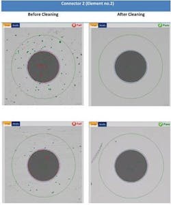
Figure 4 shows Connector 2 before and after cleaning. It is interesting to note that the contaminant here is not grease or oil from the technician’s fingers, but simply dust collected from the environment (e.g., drywall, concrete, skin particles, and sand). Therefore, even when a technician does not touch the connector endface, it can still be contaminated.
Impact on OTN bit error rate tests
Another example involves erratic readings during 40G or 100G Optical Transport Network (OTN) bit error rate tests (BERTs). Dirty connectors reduce the signal-to-noise ratio (SNR) at the receiver, and most PIN receivers react the same way to noise: with a proportional increase in BER. Problems such as forward error correction (FEC), alarm indication signal (AIS), or backward defect indicator (BDI) may also occur and lead to the unnecessary troubleshooting of Tx and Rx equipment. This means sending a technician to the site to retest the link to obtain clear results. This can be a very time-consuming, especially when you consider that a BERT needs to be error-free for 24 hours.
Case in point, a major operator in America used pre-installed fibers to deploy a 40-Gbps system across three states in 2013. They were using the “clean and connect” method without any inspection. They had to perform three BERTs because errors were showing up after 14 hours of testing.
The lesson here is that paying attention to fiber inspection will save time and eliminate the need to perform additional BERTs.
Impact on ORL
Every system has a maximum ORL, and clean connectors are vital to it. One area where ORL can be extremely detrimental is in high-speed coherent transmission (40G and 100G transport). In most of these deployments, whether they are greenfield or brownfield, low loss amplification is required to optimize distance. This means deploying a mix of Erbium-doped fiber amplifiers (EDFA) and, more recently, Raman amplifiers.
Raman is a low-noise amplification technique that uses the fiber itself as the amplifying media. It can easily be added to any existing infrastructure with little engineering. However, since the fiber is the amplifier, all light traveling within it will be amplified (i.e., both the signal and unwanted reflections). Reflections must therefore be kept to a minimum in every Raman-amplified system.
Getting the right result
To recap, false positives and the four examples above can be avoided by implementing the best troubleshooting and maintenance practices, which includes proper connector inspection and cleaning.
In today’s telecommunication environment, where opex is the name of the game, long, tedious, and ultimately misdirected troubleshooting efforts are unwelcome. Field technicians and engineers will waste precious time looking for issues at the fiber level (macrobends, splice points) or the transmission level (transmission and receiving cards) before checking the connectors. A fiber inspection probe that not only analyzes the connector endface image but auto-centers, auto-focuses, and freezes it will ensure the integrity and repeatability of inspection results.
Francis Audet is advisor, CTO Office, Vincent Racine is product line manager, and Gwennaël Amice is senior application engineer at EXFO Inc.
