Complex coding concepts for increased optical bit transfer efficiency
In the first article of this series, which appears in the July/August 2013 issue of Lightwave, we found that more efficient techniques than on/off keying (OOK) for transferring bits over the existing fiber infrastructure must be employed to meet the challenges of the cloud revolution and the resulting data avalanche. WDM, for example, has been used very successfully to increase the number of bits transferred over a single fiber; now polarization-division multiplexing (PDM) is being added to double the capacity as well. Both strategies have in common that on each channel or in each polarization plane, only one bit is encoded with a state of the signal, representing a “symbol.”
This is where complex transmission comes into the game and demonstrates its huge potential. Instead of transmitting a binary data stream, several bits can be coded to a new symbol, and a stream of these symbols can then be transmitted. Figure 1 illustrates this for 2 bits being coded to one new symbol. In this way, twice the amount of data can be accommodated in the same bandwidth.
represented by one alphabetic symbol.
Of course, with this knowledge one can imagine schemes where a much larger number of bits are defined by a single symbol that enables a data rate many times greater than in OOK, where a series of ones and zeroes is transmitted.
How does this happen in practice?
In OOK, the approach is basically that when the laser source is turned on, this is interpreted as a “one,” and when it is turned off, this reflects a “zero.” In other terms, when the light amplitude exceeds a certain level, this is a one, and a zero is when the amplitude falls below this level.
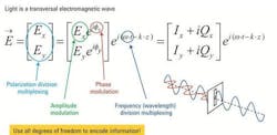
But as a light wave is defined by more parameters than just amplitude, we also have more possibilities to encode information by using all of the light wave’s degrees of freedom. Figure 2 shows the mathematical description of the electric field of an electromagnetic wave with two polarization components Ex and Ey. These orthogonal components are used in PDM as two different channels to transfer independent signals. In WDM, different frequencies ω are applied as different channels for independent data transfer at these frequencies/wavelengths. For complex modulation schemes now, additionally to the amplitude E, the phase Ф of a light wave is modulated for defining the above described symbols.
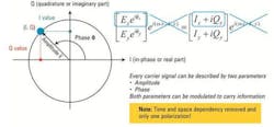
The electric field of the modulated light wave can also be described in the complex plane with an I/Q diagram. Here, I is the in-phase or real part and Q the quadrature or imaginary part as shown in Figure 3 (after removal of time and space dependency of the wave and for one polarization plane only). A symbol corresponds to a point (also called a “constellation point”) in this diagram (which itself also is referred to as a “constellation diagram”) and is defined by a Q and an I value or in polar coordinates by amplitude E and phase Ф. The constellation points correspond to the symbol clock times and are also called “detection decision points.”
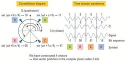
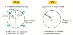
Figure 4 shows the constellation points for the four symbols in quadrature phase-shift keying (QPSK), a complex modulation type where the four symbols encode 2 bits each. The constellation points are situated on a circle with radius E. This means that the symbols only differ in phase (always π/2 between the neighboring points), not in amplitude. In the time domain, the four symbols are reflected by a combination of two waves of the same amplitude and different phase.
phase shift keying, or QPSK).
Conventional OOK can also be represented by a constellation diagram. As information is in amplitude only, the bit value 1 can be anywhere on a circle with radius (= amplitude) E (see Figure 5).
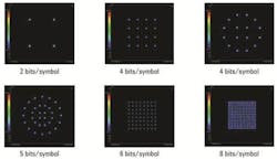
We mentioned that you can think out plenty of schemes where many more bits are encoded in one symbol, and of course different ways to implement this as well. Figure 6 shows only a selection of possible coding schemes.
So how do you decide which coding scheme to use in practice? We’ll address this and more in the next article in our series, “Which Optical Modulation Scheme Fits Best to My Application?” in the September/October issue of Lightwave.
Stephanie Michel is technical marketing engineer in the Digital Photonic Test Division of the Electronic Measurements Group at Agilent Technologies.
Figures courtesy of: Oliver Funke, Stephanie Michel, Dr. Bernd Nebendahl

